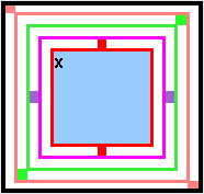
Consider the 4 framed "gyroscopic" lattice in the top diagram along with its description to be a visual abstraction of something that could be embedded in an electronic device (like a graphics calculator).
Assume that each rotation
can be programmed with a function having a forward or backward value, and that the effect of such an operation can be monitored on its central panel.
The axial rotations available are:
- [V] vertical [red]
- [H] horizontal [magenta]
- [R] right-down diagonal [green]
- [L] left-down diagonal [salmon]
The smallest squares are the axial pivots.
|
|
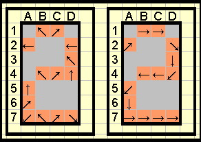
Let these general functions be incorporated into an "x*y" array of LEDs.
On this occasion each LED is programmed to represent the axial reflection of its currently held image after being "flipped" ... but then ... the image is rotated 45° clockwise immediately.
The numeral "2" has been 'scrambled' by the device in a 4*7 display at the left.
What set of operations, per individual cell, is needed to produce the outcome at the right?
The arrows are to represent the direction of writing the digit.
For cell A2, "[L]" would produce the desired end result. The rotation would face the image upwards and then a 45° clockwise rotation would occur. |
|
(In reply to
Solution (I hope I got the pivoting correct] by Dej Mar)
Um??
I should have considered your format for my solution but went according to how one would write it.
I posted this soon after Dej Mar made his initial post:
"I think we have orientation difficulties.
My [V] rotation, using the red blocks as pivots would place the "x" at the top right corner with the 'embed' image then rotated 45� so that D4 would be pointing in the reverse direction to my D4 destination. "
Some 12 hours later I was wondering what I had been thinking, I was seeing some different outcome, and then I saw the edit notice! like which will appear below this.
Edited on May 18, 2008, 12:37 am
|
|
Posted by brianjn
on 2008-05-17 11:50:22 |